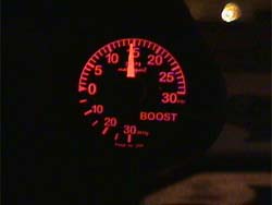

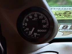
This installation is of a SPI boost gauge into my '95TT, it has dual color illumination, if yours is similarly equipped, you'll have to decide ahead of time which wire produce what results. This install goes into very little detail on the electrical connections.
Timing:
none
Special Tools:
Drill with 3/8" bit
Other Parts:
Additional vacuum hose
1 hose 'T' & 1 'barrel' connector
Additional electrical wire
Electrical crimps & connectors (I recommend an in-line fuse too)
Installation:
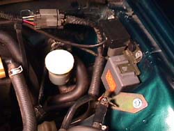
1. Unbolt the factory boost pressure sender (black box) & the wiper relay (gray box) from the fenderwall (2 x 10mm & 1 plastic screw) (1.). This exposes the fuel re-circulation canister.
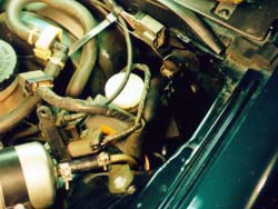
2. Unbolt the re-circulation canister from the fenderwall (2 x 10mm) & lean it up against it's hoses (2.). Wire it back to expose the grommet for the hood release cable (3.).
3. Hold the A-pillar mount to the A-pillar trim. Mark the location where the mount will be attached permanently for reference later.
4. Remove the driver's side A-pillar trim by gently pulling on it from the top by the sun visor. There are 3 clips holding the trim to the metal.
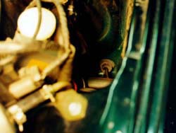
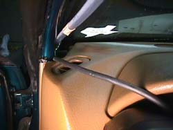
5. Route the boost hose from the dashboard opening at the bottom for the A-pillar trim down to the kick panel (4.).
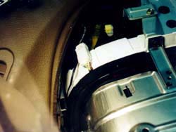
6. Find the hood release cable under the dash, follow it to the firewall. Route the hose through the firewall using the hood release hole & grommet (5.).
7. Pull the hose until enough length is through to attach to the manifold. Route the hose under the wiper relay and then over to the intake manifold.
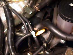
8. Remove the vacuum hose from the manifold, cut off about 1.5" to accommodate the hose 'T'. Of that 1.5", cut off .5" to make up the distance the 'T' will use. Attach the vacuum hose back to the intake manifold & attach the new boost hose to the other end of the 'T' (6.).
9. Reattach the re-circulation canister & the sensors to the fenderwall.
10. Drill a 3/8" hole in the A-pillar where the hose & electricals can easily be routed from the back of the gauge to the inside of the trim piece (7.).
Steps 11-16 are for gauges that have electrical connections for illumination.
11. Crimp connectors of choice to the short leads of the gauge.
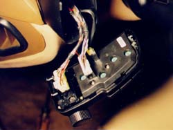
12. remove two phillips screws on the bottom of the left side control 'pod', let the 'pod' hang forward by it's wiring harnesses.
13. Remove the two phillips screws on the underside of the gauge cluster hood & remove it, to allow access to the backside of the gauge cluster.
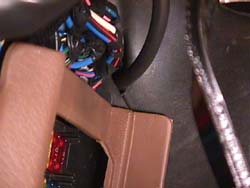
14. Splice illumination wires to the middle wire plug on the 'pod' (8.). The red wire w/ yellow stripe & silver hash marks is positive & the green wire w/ red stripe & no hash marks is ground (for '95) from the illumination dimming rheostat. Don't forget the in-line fuse on the positive wire to the gauge.
15. Route the illumination wires back to the gauge cluster & then over the plastic re-enforcement under the dashboard to the A-pillar opening (9.).
16. Crimp connectors of choice to the illumination wire.
17. Attach the mount to A-pillar in marked position. If the mount came with 3M trim tape on it, use that. Make sure there's no vinyl dressing on the trim piece, the trim tape won't stick well enough to support the weight of the boost gauge & attachments. If it doesn't, the easiest way other than the tape, or more solid way, would be to use blind pop rivets.
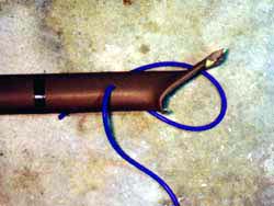
18. Cut a short length of hose to run from the gauge through the A-pillar trim piece a few inches.
19. Put the gauge close to the mount & route the wires through the hole in the trim, then from the inside of the trim, route the short hose through the trim, into the mount. Plug the hose onto the boost gauge. Slide the gauge into the opening & pull the excess wires & short hose out of the trim hole.
20. Cut the excess hose from the engine to length. Using a 'barrel' connector, plug the hose from the engine to the short hose on the gauge & plug the illumination wires into the correct wires from the lighting 'pod'
21. Snap the A-pillar trim back onto the metal. Replace the gauge cluster hood & lighting 'pod' (10.)
I like the SPI's look, but I don't like the illumination colors (orange or green). I'm trying to get rid of the color & just have plain white light to match the dash.
Special thanks to Henri Le Hir for discovering the hood release grommet as an easy way through the firewall & proofing the page & to Kyle at SGP letting me know what that little gray box is & proofing the page.
DamonZ
Back to Tech page
© Twin Turbo Zs of
Dallas - All Rights Reserved 1998
2.
3.
4.
5.
6.
7.
8.
9.
10.
11.