
After about 60k miles, the suspension on the Z32 starts to get worn. This article specifically covers building one of the more popular aftermarket setups for the TT, Eibach ProKit Springs (0.8" drop) on OEM shock bodies to retain the adjustable suspension. It can easily be adapted to building a fully OEM setup or using Kayaba AGX/Tokico Illumina adjustable shocks, etc. Freshening up all the related rubber parts along with the shocks and springs will ensure a noise free ride after the installation. Worn out rubber components can cause a collection of problems from misalignment to odd noises. This installation is on a 1990 TT.
If using the Eibach springs to lower the car, the rear camber should be adjustable enough to get the rear back in spec. during alignment. For the fronts, if the alignment has been in spec. before performing this procedure the 300 Degree Front Camber Compensation kit 300D-001 will bring the front back into spec. If there has been some camber alignment problems, investigate some of the more expensive adjustable upper links to get the alignment back in spec. Also, caster can be adjusted on the front through use of adjustable tension rods.
Part Numbers:

Part numbers courtesy of CourtesyParts.com for on-line parts ordering.
TT:
56110-30P25 Front Right Shock Body TT $584.63 Use an aftermarket Kayaba AGX/Tokico Illumina shock for less money. The Sport/Touring adjustability will be lost, but how often did it get used anyway?
56111-30P25 Front Left Shock Body TT $584.63
54010-33P21 Front Spring TT (2 req'd) No Longer Available (NLA) Use an aftermarket Eibach/Tein lowering springs
54050-33P20 Front Bump Stop (2 req'd) $49.87
54055-33P20 Front Dust Boot (2 req'd) $23.44
54320-30P00 Front Upper Insulator Right TT (2 req'd) NLA Use the 54320-33P20 Front Upper Insulator NA (2 req'd)
NOTE: Nissan's part numbers are correct, the product they ship is not correct. The parts listings denote there should be a 54320-30P00 and a 54321-30P00 as a R/L set. The part shipped as 54321-30P00 is actually the 54320-33P20 Front upper insulator for the NA. Buy two of the 54320-30P00 instead, the R/L parts don't exist anymore.
54329-33P00 Front Upper Red Insulator Gasket (2 req'd) $8.49
56210-30P25 Rear Shock Body TT (comes with dust boot/bump stop, metal mid plate, rubber insulator, top washer and lock nut) (2 req'd) $307.41
55020-33P10 Rear Spring TT (2 req'd) NLA
55034-71L10 Rear Rubber Spring Seat (2 req'd) $24.48
56218-33P00 Rear Star Rubber Insulator $9.20
08912-7421A Rear Retaining Nut $0.64
55338-35F00 Rear Upper Red Insulator Gasket (2 req'd) $20.66
2 seater NA:
56110-33P86 Front L/R Shock Body NA (2 req'd) NLA
54010-33P11 Front Spring 2 Seater NA (2 req'd) NLA
54050-33P20 Front Bump Stop (2 req'd) $49.87
54055-33P20 Front Dust Boot (2 req'd) $23.44
54320-33P20 Front Upper Insulator NA (2 req'd) $40.80
54329-33P00 Front Upper Red Insulator Gasket (2 req'd) $8.49
56210-33P25 Rear Shock Body NA (comes with dust boot/bump stop, metal mid plate, rubber insulator, top washer and lock nut) (2 req'd) NLA
55020-VP110 Rear Spring 2 Seater NA (2 req'd) NLA
55034-71L10 Rear Rubber Spring Seat (2 req'd) $24.48
56218-33P00 Rear Star Rubber Insulator $9.20
55338-35F00 Rear Upper Red Insulator Gasket (2 req'd) $20.66
4 seater NA:
56110-33P86 Front L/R Shock Body NA (2 req'd) NLA
54010-33P20 Front Spring 4 Seater NA (2 req'd) NLA
54050-33P20 Front Bump Stop (2 req'd) $49.87
54055-33P20 Front Dust Boot (2 req'd) $23.44
54320-33P20 Front Upper Insulator NA (2 req'd) $40.80
54329-33P00 Front Upper Red Insulator Gasket (2 req'd) $8.49
56210-33P25 Rear Shock Body NA (comes with dust boot/bump stop, metal mid plate, rubber insulator, top washer and lock nut) (2 req'd) NLA
55020-32P02 Rear Spring 4 Seater NA (2 req'd) NLA
55034-71L10 Rear Rubber Spring Seat (2 req'd) $24.48
56218-33P00 Rear Star Rubber Insulator $9.20
55338-35F00 Rear Upper Red Insulator Gasket (2 req'd) $20.66
Optional:
56115-33P50 Front Upper Shock Mount $47.50
56117-33P20 Front Upper Retaining Plate NA NLA
56117-30P00 Front Upper Retaining Plate TT NLA
54397-86E01 Front Actuator TT NLA
54396-30P00 Front Actuator Bracket TT NLA
08360-5142D Front Actuator Screws TT (2 req'd ea. side) $1.10
01225-00231 Front Upper Mounting Nuts (2 req'd ea. side) $1.20
01225-00491 Front Lower Mounting Nut $5.01
55322-35F11 Rear Upper Shock Mount NA NLA
55322-30P00 Rear Upper Shock Mount TT NLA
54397-86E11 Rear Actuator TT NLA
54396-72L00 Rear Actuator Bracket TT NLA
08360-51426 Rear Actuator Screws TT (2 req'd ea. side) NLA
01225-00102 Rear Upper Mounting Nuts (2 req'd ea. side) $0.54
56226-33P00 Rear Lower Mounting Bolt $17.50
01225-00491 Rear Lower Mounting Nut $5.01
56217-RS580 NISMO Rear Shock Upper Rubber Insulator (2 req'd) NLA
56218-RS580 NISMO rear shock lower star rubber insulator (2 req'd) NLA
Special Tools:
Bench Vice large enough to handle shock bodies (I have a 6" vice for example)
Proper spring compressors
1/2" air impact wrench
tire iron/prybar
Procedure: NOTE: The Z32 does NOT have 'Macpherson' struts, but Macpherson strut compressors should be able to handle the spring rates.**Understand if an accident happens, you could die**, Springs with this much potential energy built up can easily kill a person if a compressor comes off, or breaks. As always, wear safety glasses and shop gloves. I cannot stress this enough, this is not something to be a cheapskate with. Even if you only use it once, spending $80 on a quality set of compressors vs. going to the hospital for whatever reason isn't an option. Spend the money. Do not rent a set of compressors, these are going to be abused and closer to failure. Spend the money. I have personally used the NAPA heavy duty compressors multiple times without even a hint of incident, the first set of cheapies almost cost me in a big way due to failure. I've learned several lessons for you during all the TECH articles I've written. I didn't want to release this one for a long time because of the hazards involved. Pay attention to what I tell you to do & how to do it and what your doing. Common sense will get you through, if you don't have any... don't pass Go, don't collect $200. Take the money for the hospital bill & get a pro to do the work for you. I'm NOT responsible for your actions, you are.
❑ Roll the trunk carpet edges up to access trim nuts, and the spare tire cover.
❑ Remove the center rear plastic trim piece (2 x plastic screws, 2 x 10mm nuts) (1.).
❑ Remove the taillight covers in the corner trim pieces (snapped in place) (2.).
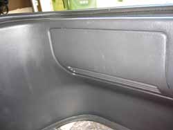
❑ Remove the corner trim pieces (4 x 10 mm nuts, 4 x phillips screws) (3.).
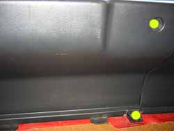
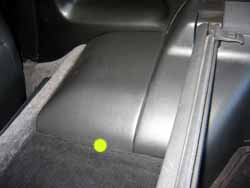
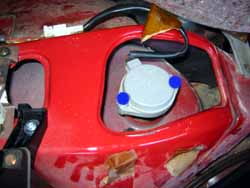
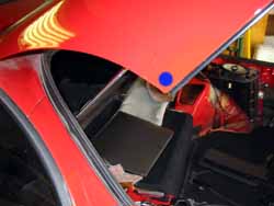
❑ Remove the trim covers behind the seats (coupe) where the 'suction cup' thing is and the ABS actuator on the other side. They simply unsnap by prying up where the yellow dot is in image (4.).
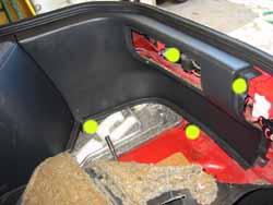
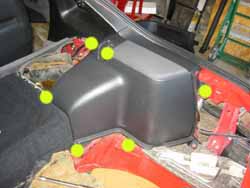
❑ Remove the trim pieces covering the shock towers (8 x phillips, 4 x 10 mm buts) (5., 6. & 7.).
❑ Remove the insulation strips over each shock tower.
2. Lift the car:
❑ Break loose all lug nuts (20 x 21mm).
❑ Get the car in the air, enough to get the tires off the ground. Make sure all jack stands are properly placed, & all safety measures are taken.
❑ Remove the lug nuts & wheels.
2.
3.
4.
5.
6.
7.
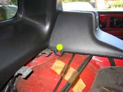
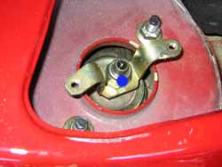
❑ If on a TT, remove the actuator from the top of the shock (2 x phillips/8 mm bolts) (8.).
❑ Remove the actuator bracket (1 x 12 mm nut) (9.).
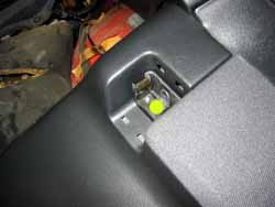
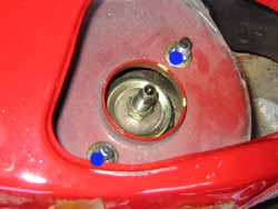
❑ For both NA/TT: DO NOT remove the lower 14mm nut in the center. This will let the captive spring loose and can cause serious injury!.
❑ Remove the outside upper shock mounting nuts (2 x 12 mm nuts) (10.).
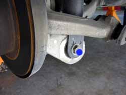
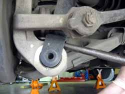
❑ Remove the lower shock mounting bolt (1 x 17 mm nut & bolt) (11.). The shock will still be firmly in place because of spring tension. Use a tire iron or some solid prybar to pry the lower shock mount off the aluminum hub assembly (12.).
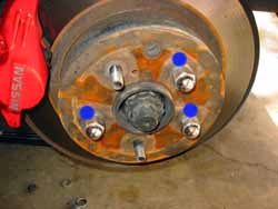
❑ Put 3 of the lugnuts back on to hold the rotor in place (13.). Pull the parking break to lock the rear rotors onto the hubs. I hook a finger into one of the top coils of the shock, place a foot on the rotor hat and stand on it to lower the control arm far enough to get the upper shock studs out of the shock tower.
NOTE: Do not step on the top of the rotor, this will bend the splash shield behind the rotor. Step on the rotor hat instead. This might require some bouncing on the rotor to get enough clearance. Watch your fingers and watch your head and shoulders around the pointy part of the opened rear deck lid (14.).
❑ Be careful with the paint on the car when removing the shock from the wheel well.
9.
10.
11.
12.
13.
14.
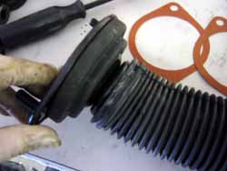
❑ Wrap the shock body in a rag to keep it from scratching while it's in the vice (old or new).
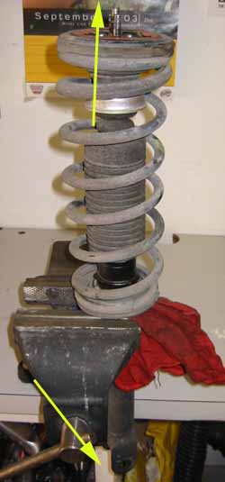
❑ Orient the spring upwards, and make the two studs on the top line up perpendicular to the bench (upper arrow in 15.). This is very important for getting the orientation from the top studs to the bottom bolt correct when rebuilding the shock (bottom arrow in 15.). If you have to, draw the angles on paper so they are not forgotten. It's easy to get distracted during this. If the orientation is not correct, the shock will not fit back in the car. The rears are hard enough to do when the angle is correct because of clearanaces.
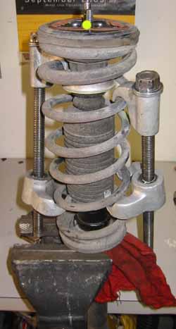
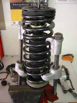
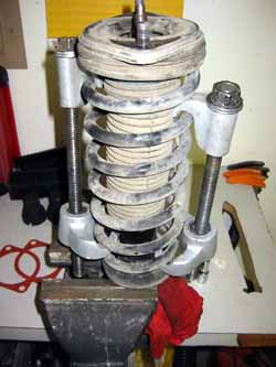
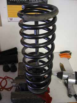
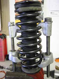
❑ Install the spring compressors on opposite sides of the spring (16.). Adhere to all safety instructions included with the spring compressors.
❑ Once the compressors are affixed to the springs as high & low as possible, tighten them down a bit. Notice they will be slightly set at an angle if they are like the ones in the image (from NAPA), the coil of the spring forces the angle, which is fine. Just make sure they have clearance below for the threaded parts to miss the vice jaws. The compressors don't have to squash the spring, the idea is to trap the coils with the compressors and then the only part that can release would be any coils not caught by the compressor (maybe 2?).
❑ Once some tension has been placed on the spring compressors, then remove the top nut on the shock shaft (1 x 14 mm nut) (yellow dot in 16.).
Keep in mind that if something breaks where the spring is going to go... straight up more then likely. Keep hands and heads from out of the path if something were to happen.
❑ Remove the top shock plate (1 x 14 mm nut). The spring is totally kept by the spring compressor now.
❑ Remove the upper mounting plates, dustboot and bumpstop from the shock shaft.
❑ Slowly back the compressors off a little bit on each side with the air wrench until tension is fully removed. If tension won't be fully relieved before the threaded part comes out of the compressor (in other words the compressor fails), clamp it back down and bolt the top plate back on tight, reset the compressors in a manner where they will allow full extension of the spring (about an additional 2-3" height).
❑ Note the orientation of the shock body bolt holes at the bottom in relation to the vice and bench. Put the new shock body in the vice the exact same way wrapped in a rag to keep from scratching the shock body. Double check the orientation.
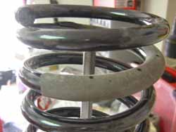
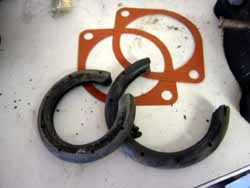
❑ If possible, reuse the rubber coil insulators from the old springs (17. & 18.).
❑ Put the dust boot/bump stop on the shock shaft (19.).
❑ Put the metal cap on the dust boot, lining up the two keyways on the rubber (20.).
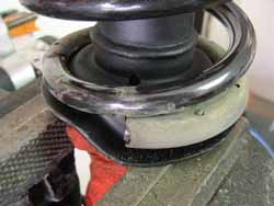
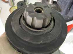
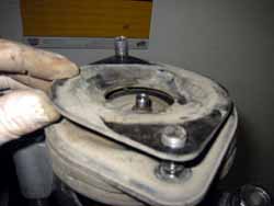
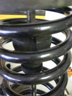
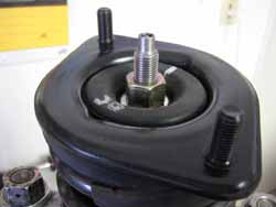
❑ Assemble the top mount. The upper spring insulator rubber doughnut has curves that align with the bottom of the metal top mount (21.).
❑ There is a metal sleave that goes up the middle for the TT. It holds the 'star' rubber insulator to the bottom of the mount (22.) and the 'barbell' one to the top (23.). These rubber parts are now NLA, so use the NA parts which are smaller diameter hole and doesn't require the sleave. Just stack them onto the shock shaft with the top mount. The lip on the star insulator and the lip on the barbell go toward the mount.
❑ The rear springs are the ones with the smallest end coil of the four. If installing the Eibach set PN 130138-6320.002. Generally they package the rears on the outsides of the four in the box. If using OEM, just check the part numbers to make sure the right springs are going on the right ends. The 'smaller' end of the overall larger spring goes toward the bottom. Put the new spring on the shock body and line up the bottom coil end in the pocket on the shock body (18.).
❑ Set up the compressors like when removing the spring. Set them where they are grabbing the coils as high and as low as possible (24.). This time around the spring will have to be compressed, not just captured. Make sure there is clearance for the threaded part of the compressor underneath when the tool is run down to compress the spring. Use the air wrench to slowly run down each side a little at a time keeping the compression as even as possible on each side. Continue until the upper rubber insulator and plate can be placed on top of the shock shaft and reveals enough thread to get the new retaining nut on and tightened down a bit by hand.
❑ The upper metal washer should go on with the outer edges going up.
❑ The retaining nut for the TT is the short 14mm, NOT the nylock 14mm supplied with the new OEM shock body. For TT's this is critical. The slim nut is used to maintain proper height for the actuator when it's mounted. For NAs, just use the nylock nut. For AGX/Illumina installations, use the provided nut with the shock.
❑ Check the alignment of the studs on the upper mounting bracket to make sure they are perpendicular to the bench as they should be.
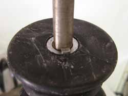
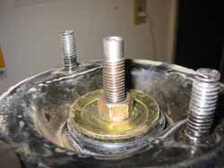
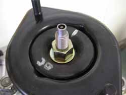
❑ There's no real way to torque the retaining nut. Run it down with the air wrench. Image (25.) shows the correct amount of threads exposed on the shaft for a OEM TT rear shock. I'm not sure about the amount for the OEM NA. Probably the same as the image shows, but the top part won't be round, it will have flat sides (where it could be held it with a small wrench). If the nut could be torqued, it would be 14-19 ft lbs., not a lot.
❑ Slowly uncompress the spring from side to side until the compressors can be removed from the spring. Again, make certain the studs on the upper mount are perpendicular to the bench as they should be for proper orientation.
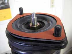
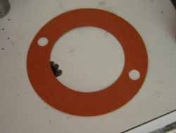
❑ Put the red gasket on the top over the studs (26.).
7. Install the shock assembly:
❑ Carefully put the shock assembly back into the general position.
❑ Get the bottom on the hub assembly mount. There are two dots on each side of the shock body's mount that will hold the shock body at the correct height when engaged with the metal sleave in the hub's lower bushing.
❑ Slip the bolt into the hole and hand tighten the nut on a few threads.
❑ Standing/bouncing on the rotor hat again will get the top back in place. Again, be careful with your fingers. Put a long socket in from the inside of the cabin onto the retaining nut and carefully pull the shock in place while bouncing.
❑ Torque the top shock nuts to 12-14 ft-lbs. (2 x 12 mm nuts) (10.).
❑ Use the floor jack to lift the lower suspension arm to as close to parallel as the weight of the car will allow. When the body is just about to lift off the jackstand in that corner lock the jack in place and torque the bottom to 57-72 ft-lbs (17 mm nut/bolt) (11.). This preloads the lower shock bushing as it will be when it's bearing weight.
8. Repeat for the other rear corner.
9. Replace the TT actuators if equipped/required:
❑ Replace the actuator brackets (2 x 12 mm nuts) (9.). Torque to 14-19 ft-lbs.
❑ Check the orientation of the actuator slot and match it to the blade in the top of the shock shaft. Rotate the actuator until it aligns with the bracket and the wires will still reach. Install the actuators (4 x phillips/8 mm bolts) (8.). If there is a clearance or cable length problem, remove the actuator and put a wrench on the top nut, rotate it clockwise until the bracket would be oriented the way it needs to be for everything to fit.
10. Replace the rear interior trim:
❑ Installation is the reverse of the removal.
18.
19.
20.
21.
22.
23.
24.
25.
26.
❑ If there is a front strut tower brace, remove it.
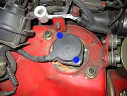
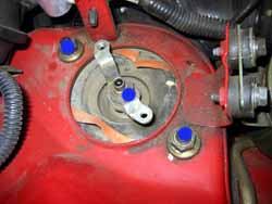
❑ If on a TT, remove the actuator from the top of the shock (2 x phillips/8 mm bolts) (27.) and remove the actuator bracket (1 x 17 mm nut) (center dot in 28.). On both the NA and TT: DO NOT remove the lower 19 mm nut in the center. Like on the rear shocks, this will let the captive spring loose and can cause serious injury!.
❑ Remove the upper shock mounting nuts (2 x 14 mm nuts) (outside dots in 28.).
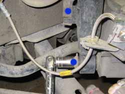
❑ Remove the bolt holding the brake line bracket to the lower shock body (1 x 10 mm) (upper dot in 29.).
❑ Remove the dirt cover on the stud threads for the lower shock nut. Use the jack under the lower control arm to compress the shock and allow room to get a socket/breaker bar on the lower nut (1 x 17 mm) (lower dot in 29.).
❑ The shock will still be firmly in place because of spring tension. Use the tire iron to pry the bottom of the shock body off the hub assembly stud. Keep a hand on the spring, it will want to fall down and snag the brake line (seen in 29.).
❑ Carefully remove the shock from the wheel well.
12. Place the shock in the bench vice:
❑ This works exactly like it did for the rear shocks. Wrap the shock body in a rag to keep it from scratching while it's in the vice (old or new).
❑ Orient the spring upwards, and make the two studs on the top line up perpendicular to the bench. This is very important for getting the orientation from the top studs to the bottom bolt correct when rebuilding the shock. If you have to, draw the angles on paper so they are not forgotten. It's very easy to get distracted during this procedure. If the orientation is not correct, the shock will not fit back in the car. Also note which side the shock body is from on the car. There is a L and R side for the fronts on the TT.
28.
29.
❑ Install the spring compressors on opposite sides of the spring (30.) Adhere to all safety instructions included with the spring compressors. Once the compressors are affixed to the springs as high & low as possible, tighten them down a bit. Again, they don't have to squash the spring, just trap it.
❑ Once some tension has been placed on the spring compressors, then remove the top nut on the shock shaft (1 x 19 mm nut). Keep in mind that if something breaks where the spring is going to go... straight up more then likely. Keep hands and heads from out of the path if something were to happen.
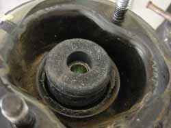
❑ Remove the top shock mount and dust boot etc. Note there is a plate on top of the assembly, it's critical it goes back on after assembling the new shock (31.).
❑ The spring is totally kept by the spring compressor now. Slowly back the compressors off a little bit on each side until tension is fully removed. If tension won't be fully relieved before the screw comes out of the compressor (in otherwords the compressor fails), clamp it back down and bolt the top plate back on tight, reset the compressors in a manner where they will allow full extension of the spring (about an additional 2-3" height).
31.
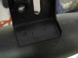
❑ On the TT Use the corect shock body for the left or right side. There will be a L or R stamping on the brake line bracket to note which is which (32.).
❑ Note the orientation of the shock body bolt holes at the bottom in relation to the vice and bench. Put the new shock body in the vice the exact same way wrapped in a rag to keep from scratching the shock body. Double check the orientation.
❑ If possible, reuse the rubber coil insulators from the old springs (black bits in 33.).
❑ The small end of the spring goes toward the bottom. Put the new spring on the shock body and line up the bottom coil end in the pocket on the shock body (34.).
❑ Put the bump stop on the shock shaft (35.).
❑ Put the new dust boot on the bottom of the upper mounting plate (36.).
❑ For the TTs, on the upper insulator, I will put a marking to show where the little indexing nub is on the outside of the insulator (white line on the upper right in 38.). This style of upper insulator is NLA>. Use the NA upper insulator as a universal replacement part.
❑ Set up the compressors like when removing the spring. Set them where they are grabbing the coils as high and as low as possible (37.). This time the spring will have to be compressed, not just captured. Make sure there is clearance for the threaded part of the compressor underneath when the tool is run down to compress the spring. Use the air wrench to slowly run down each side a little at a time keeping the compression as even as possible on each side. Continue until the upper rubber insulator and the gold washer can be placed on top of the upper shock mount and the shock shaft reveals enough thread to get the new retaining nut on and tightened down a bit.
❑ Check the alignment of the studs on the upper mounting bracket to make sure they are perpendicular to the bench as they should be.
❑ There's no real way to torque the retaining nut, the manual calls for 25-33 ft lbs. For the OEM TT run it down until there's about 3/8" of threads exposed as shown in (38.), NAs are probably about the same. NAs just use the nylock nut, TTs have a regular retaining nut, then the nylock nut goes on with the actuator.
❑ Slowly uncompress the spring from side to side until the compressors can be removed from the spring. On the TT, twist the shock shaft with a 19 mm socket until the marking made earlier on the upper insulator points to one of the dimples in the upper shock mount (white line on the upper right in 39.).
❑ Put the upper retaining plate on top and then the red insulator gasket on the very top of the shock assembly (40.).
15. Install the shock assembly:
❑ Carefully put the shock assembly back into the general position. The trick is to put the bottom in place and hold it in place with the washer and nut hand tightened, then push the top into place. With the Eibach springs this is a little easier because the height is just low enough to make it easier then stockers.
❑ Replace the strut tower brace if required.
❑ Torque the top shock nuts to 23-31 ft-lbs. (2 x 14 mm nuts) (outside dots in 28.).
❑ Use the floor jack to pick up the lower control arm the same way as the rears to preload the arm and torque the bottom nut to 72-87 ft-lbs (17 mm nut/bolt) (lower dot in 29). Reconnect the brake line to the shock body (1 x 10 mm bolt) (upper dot in 29). Replace the dirt shield on the lower stud.
16. Repeat for the other front corner.
17. Replace the TT actuators if equipped/required:
❑ Replace the actuator brackets (2 x 14 mm nuts) (center dot in 28.).
❑ Check the orientation of the actuator slot and match it to the blade in the top of the shock shaft. Rotate the actuator until it aligns with the bracket and the wires will still reach.
❑ Install the actuators (4 x phillips/8 mm bolts) (27).
18. Replace all 4 wheels:
❑ Finger tighten the lugs. Return the car to the ground.
❑ Torque the lugs in a skip 1 pattern to 78 ft-lbs (20 x 21 mm lugnuts).
© Twin Turbo Zs of Dallas - All Rights Reserved 2021
33.
34.
35.
36.
37.
38.
39.
40.