
Procedure:
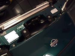
1. Remove the nose panel between the headlights (4 or 2 x 10mm/phillips) (1.). Be careful not to loose the 'U' spacers (2.) if they are still with the car.
2. Disconnect the MAS sensor's plug, being careful not to loose the small wire clip holding it in place.
3. Remove the 10mm nut on the 'top' of the filter (should be poking through the plastic splash guard). Loosen the hoseclamps on either end of the large plastic 'T' holding the MAS & filter in place (2 x 8mm hoseclamps). Remove the single POP filter/MAS/'T' assembly (3.). Stuff rags in the intake tubing to keep anything from falling into the hardpipes.
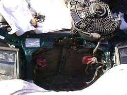
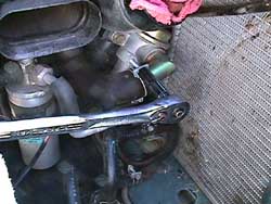
4. Remove the bolts holding the oilcooler in place (3 x 12mm). 'Flip' the cooler forward (4.).
5. Remove the electric radiator fan (2 x 10mm) (5.) & 'Flip' the fan assembly out of the way (6.).
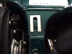
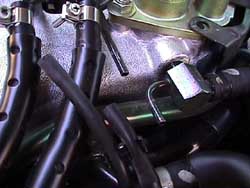
6. My '95 has a different boost sensor then earlier years (7.), disconnect the sensor's plug & remove the boost hose going to the sensor. Use a screwdriver to pry the sensor off it's mount & remove it.
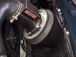
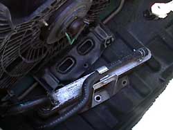
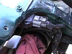
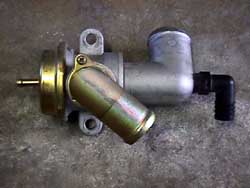
7. Loosen the hoseclamps on the passenger side recirculation (surge) valve (2 x 10mm) (8.). Move the squeeze clamp up the vacuum hose on the top of the valve & disconnect it. Remove the recirculation valve (2 x 12mm).
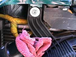
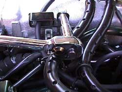
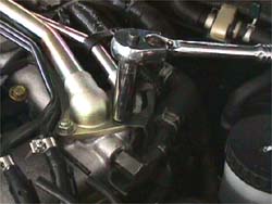
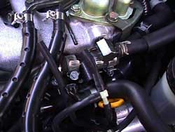
8. Disconnect the vacuum lines on the driver side of the plenum (9.). Remove the cruise control bracket (10.). Remove the bolts holding the rear of the idle air tube (11.).
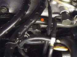
9. Move the clamp on the front rubber hose back on the idle air tube. It's easier to keep the rubber hose on the rear of the tube & disconnect it where it meets the idle air valve on the back of the plenum instead of taking it off the tube. Remove the two plastic clips holding the wire harness in place. Use a straight blade screwdriver to push in the tab & then slide the clip off the brackets on the bottom of the idle air tube. Remove the idle air tube (orange dot 12.).
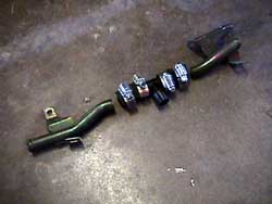
10. For most people, the recirculation valve will need to be taken to a machinist to have the bottom tapped for the 90degree plastic elbow to be installed (13.). The idle air tube needs to have the center section removed to fit in the two rubber hoses & the plastic 'T' fitting (14.).
11. Install the plastic 'T' fitting with the orifice towards the front of the engine, with the 90 leg facing the fender into the new rubber hoses. Install the rest of the idle air tube (2 x 12mm & 2 clips). The cruise control bracket probably wont fit back on (10.), I left it off (1 x 10mm). Reconnect the 2 small vacuum lines above the 'T' fitting (15.). Tighten all the clamps. Attach the long low speed driveability hose to the third outlet of the plastic 'T' fitting. Tighten the hoseclamp on it.
12. Remove the upper radiator brackets (2 x 10mm) & lean the radiator towards the engine to snake the low speed driveability kit's hose inbetween the hardpipes and the radiator, to get it from the 3rd opening on the plastic 'T' fitting to the surge valve up front. Be patient, there is a way to get it through there. In the last pic of the installed twinpop, I have this hose running over the top of one of the pops. I had done this for a temporary install, later I did the 'around the radiator' install. Loop the end of the hose under the recirculation canister.
13. Loosely clamp the new hose on the new plastic elbow on the surge valve. Re-install the surge valve. Get the large hoses re-attached, then bolt it back to the frame starting with the rear bolt (2 x 12). Tighten all the clamps, also re-attach the vacuum hose to the top of the surge valve.
14. Reinstall the electric radiator fan (2 x 10mm) & the oil cooler (3 x 12mm). Reinstall the boost sensor if it's up front like mine.
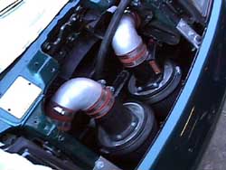
15. Remove the MAS/single POP from the large plastic 'T'. Using the orange rubber hose connections, attach the MAS/single POP to one of the silver elbows, adding the smaller orange fubber hose to the end of it. Tighten all the clamps except the one on the very end. Make a second assembly like the first, but using the dummy MAS in the middle. Remove the rags from the hardpipes. Install both assemblies on the hardpipes (remember my note on the temporarily installed low speed hose going over the top of the MAS side POP 16.). Plug the MAS back in.
16. Replace the nose panel making sure the 'U' spacers are in place (4 or 2 x 10mm/phillips).
17. Remove the ECU & install the new chip/swap ECUs for the new twinPOP program.
If a Techtom MDM-100 is available, there's some tuning that can be done to the twinPOP to make it more streetable if there are hesitation problems after installation. MAS voltage should read .95V at 850 RPM. To up the MAS voltage, make the oriface in the small plastic 'T' fitting larger. I used a 3/8" 'finishing' type washer instead of enlarging the piece JWT sent. If I botched something, I could always back up. JWT said they oriface they send with it is a .330 hole.
© Twin Turbo Zs of Dallas - All Rights Reserved 1999
2.
3.
4.
5.
6.
7.
8.
9.
10.
11.
12.
13.
14.
15.
16.