
Timing:
When the urge strikes & the pocket book is fat, this is the best time. Or when the exhaust is smoking and the diagnosis is turbo seal failure.
Parts:
2 turbos, custom, or OEM PNs 14411, 14411+A
5 Rubber water feed lines, PNs 14056W, 14056WB, 14056WA, 14056WC, 14056WD
4 Metal water feed lines, PNs 15192P, 15192R, 15192PA, 15192RA
10 Total copper seals, all PN 15188A
1 Copper seal (listed as two PNs) PN 15192G for the passenger oil feed
2 Oil feed lines, PNs 15192+A, I recommend 15192 & 15192+B as a 2 piece line, while 15192 can be a single piece line.
2 Oil return gaskets, PN 15196
2 Oil return rubber hose couplings, PN 15198
2 Intake inlet gaskets, PN ***sec.165? listed*** dunno
2 Intake outlet gaskets, PN 14456M
2 Metal turbo flange gaskets, PN 14415
2 Metal precat gaskets, PN 14445
Special tools:
1 ton engine hoist or stronger
engine stand
Procedure:
1. Remove the engine (Details).
2. Clean the engine, particularly the areas around the turbos to ensure no debris enter the new turbo housings. Engine dergeaser or brake cleaner works well.
On the driver side:
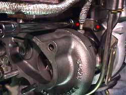
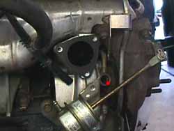
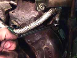
3. Remove the heat shield (3 x 10mm) (red dots in 1.). Remove the precat (2 x 13mm nuts, 2 x 13mm bolts).
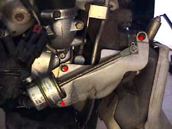
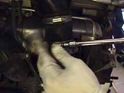
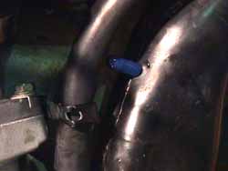
4. Remove the upper hardpipe & rubber hose coupling (1 x 10mm & 2 x hoseclamps) (2.). Remove the intake outlet (3 x 10mm & 1 x 10mm for water feed line bracket) (3.). Disconnect the boost solenoid vacuum line from the intake inlet. Remove the intake inlet (2 x 12mm). It's easy to get to this with an extension from the front. Disconnect the vacuum line from the wastegate actuator.
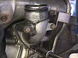
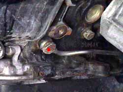
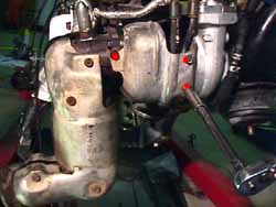
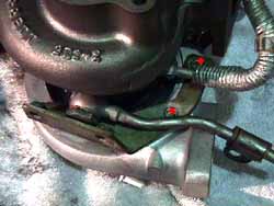
5. Trace the water lines going from the turbo. They go from the sides of the turbo upward to the block. Disconnect both rubber water lines (4 x hoseclamps), or cut them if replacing (recommended). Note the shape and orientation of each hose. Remove the water feed banjo bolt (1 x 19mm) on the outside of the turbo (red dot in 4.). Remove the bolt holding the line to the back of the block (1 x 10mm). Remove the ouside water line.
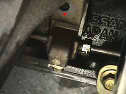
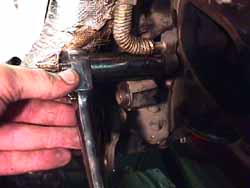
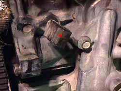
6. Remove the AC compressor bracket from the block (3 x 14mm, 1 x 12mm, 1 x 8mm). Remove the oil feed banjo bolt (1 x 19mm) from the block (red dot in 5.) behind it. Remove the midway oil feed line bracket on the motor mount (1 x 14) (red dot in 6.). Loosen the oil feed line from the turbo (1 x 12 tubing wrench).
7. Loosen the hoseclamps on the oil return line to the oil pan.
8. Bend back the tabs on the turbo flange nut locking plates. The Nissan design on these things is poor. They should have made the tabs longer to allow getting a screwdriver on them a little easier. Instead they are shorter then the height of the nuts, making them difficult to pry back. Remove the turbo assembly from the exhaust manifold (4 x 13mm). Remove the oil feed line (1 x 12mm tubing wrench). Remove the remaining water line from the turbo (1 x 19mm). Remove the oil return line (2 x 12mm) from the bottom of the turbo.
9. Install oil return line on bottom of new turbo with gasket (2 x 12mm), make sure it's pointing the right direction. Torque to 12-15 ft-lbs.
10. Install the oil feed line (1 x 12 flare nut). Approximate the angle needed to fit the lines back in place on the block. Tighten to 11-13 ft-lbs. There were two different models of oil feed tube available when I did my turbos, a 1 piece (2/90+) and a 2 piece (7/89-2/90) version. I found the 2 piece to be a little easier to work with.
NOTE: Make sure the 10mm plug is in place in the bottom of the block area of the oil feed line. It's very easy to overlook.
11 . Install the inside water feed line (1 x 19mm banjo bolt). Make sure the tubing loop under the turbo is parallel with the housings. The heat shield will cradle it when it's installed. Torque to 11-14 ft-lbs.
12. Install the outside water feed line (1 x 19mm banjo bolt). Get the bolt started, but leave the line loose, so it's mobile to get wrenches around to tighten the mounting nuts.
13. Replace the rubber coupling hose for the oil return line on the oil pan.
14. Install the turbo and new metal gasket on the exhaust manifold, make sure to get the oil return line in the rubber coupling hose. Hang the turbo by a single nut on the rear of the flange. Tighten that nut to mate the flanges. Doublecheck all the line angles to make sure everything will fit properly. Make whatever adjustments necessary.
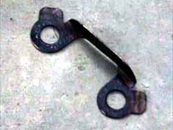
15. Install the locking plate that doesn't look like the one in picture 7. (the one pictured is for the rear flange), on the front studs of the manifold, replace the mounting nuts (2 x 13mm). Use anti-sieze compound on the nuts. Snug them up. Remove the single nut from the rear of the flange, install the locking bracket in picture 7. replace the rear mounting nuts (2 x 13mm). Torque all 4 nuts to 32-40. Bend the locking tabs down on the sides of the nuts.
16. Position the outer water feed line. Bolt the brace on the back of the block (1 x 10mm bolt). Torque the banjo bolt (1 x 19mm) to 11-14 ft-lbs.
17. Bolt the midway oil feed line bracket on the motor mount (1 x 14) (red dot in 6.). Torque to 30-38 ft-lbs. The turbo needs to be primed with oil before initial operation. Use an oil squirt can filled with standard motor oil (not synthetic, weight really doesn't matter) and start pumping oil into the end of the oil feed tube. Rotate the exposed turbo shaft from time to time until it feels 'looser' from having oil around itself. Replace the banjo bolt at the front of the oil feed line on the block (1 x 19mm). Torque to 11-14 ft-lbs.
18. Replace the AC compressor bracket (3 x 14mm, 1 x 12mm, 1 x 8mm). Torque the 14mm & 12mm bolts to 30-38 ft-lbs. Torque the 8mm bolt to 2.2-3.6 ft-lbs.
19. Install the new rubber water lines, the slightly curved one goes on the side (2 x hoseclamp), the straighter one goes on the back (2 x hoseclamp), another straight one goes at the very front of the block, where the second metal line bends upward (2 x hoseclamp). We didn't do this one on Shahram's car. Just forgot about it until I sat down with the exploded diagrams & part numbers.
20. Tighten the hoseclamps on the rubber coupling hose for the oil return line on the oil pan.
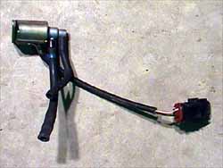
21. If installing an EVC, or if an EVC is already installed, now is the time to remove the boost solenoids (8.). They're unplugged and useless with a properly installed EVC. Remove the T in the vacuum & prep the vacuum line to go straight from the wastegate nipple to the front intercooler hardpipe. Something interesting, this hose is the same one the boost jet would go in. If you look at it close enough, there's a factory orifice already in the line, it allows the car to reach factory set 9psi!
22. Clean old gasket material off the intake outlet. Install the intake outlet (3 x 10mm), with new gasket. Re-connect the water feed line bracket. Torque all to 4.6-6.1 ft-lbs. Install new intake outlet rubber hose coupling (hoseclamp assembly or 2 hoseclamps, depending on if the assembly is still together). Leave clamps loose. Install the intake hardpipe in the other end of the coupling, bolt to plenum (1 x 10mm). Tighten the hoseclamps (2.). Stuff a rag in the open end to keep debris from entering the turbo.
23. Install the intake inlet (2 x 12mm), with gasket. Torque to 18-22 ft-lbs. Re-connect the vacuum line from the boost solenoid. If running an EVC full time, cap the nipple instead (9.). Stuff a rag in the open end to keep debris from entering the turbo.
24. Install the pre-cat and gasket (2 x 13mm nuts, 2 x 13mm bolts). Use anti-seize compound on the nuts & bolts. Torque to 18-22 ft-lbs. Install the heat shielding (3 x 10mm) (1.). Torque to 4.6-6.1 ft-lbs.
On the passenger side:
25. Remove the heat shield (3 x 10mm) (red dots in 10.). Remove the precat (2 x 13mm nuts, 2 x 13mm bolts).
26. Remove the upper hardpipe & rubber hose coupling (1 x 10mm & 2 x hoseclamps). Disconnect the vacuum line from the intake inlet. Remove the intake inlet (2 x 12mm).
27. Trace the water lines going from the turbo. They go from the sides of the turbo upward to the block. Disconnect both rubber water lines (4 x hoseclamps), or cut them if replacing (recommended). Note the shape and orientation of each hose. Remove the bolt in the rear water feed line's upper bracket.
28. Remove the oil feed banjo bolt (1 x 19mm) from the block (11.) behind it. Remove the oil feed line from the turbo (1 x 12 tubing wrench) (12.). Note: on the oil line this side got insulated in mid '92. So don't be surprised when the new part has insulation on it & the old one doesn't. All new lines sold have it.
29. Remove the lower oil return tube (2 x 12mm, 1 hoseclamp on oil pan end).
30. Twist the oil feed block coming from the block to allow room for the turbo flange to clear (red dot in 13.).
31. Bend up the locking plate tabs. Remove the turbo (4 x 13mm), use a wrench on the back two nuts & outside front (14.). Use a socket on an extension from below to get the last one.
32. Remove the intake outlet (3 x 10mm & 1 x 10mm for water line bracket). Remove the heat shield bracket from the compressor side of the turbo (2 x 10mm) (red dots in 15.).
33. Remove water feed lines from the turbo (2 x 19mm banjo bolts).
34. Install water lines on new turbo (2 x 19mm banjo bolts). Don't tighten them yet. The short one should be installed with the hose leaning outward, not inward. It should line up right next to the rear water feed line. Install the wastegate vacuum line (1 hoseclamp). Make whatever adjustments needed like the driver's side to accomodate an EVC if one is being used. Make sure the stock orifice mentioned in the driver's turbo install is used in both sides.
35. Clean off old gasket material from intake outlet. Install intake outlet (3 x 10mm). Bolt front water feed line to intake outlet (1 x 10mm). Torque all to 4.6-6.1 ft-lbs. Remove the oil pressure sensor from the oil filter bracket below the turbo.
36. Hang the turbo off the flange with gasket using the single nut technique from above from one of the rear studs. Put on the front locking plate & snug up the front nuts (2 x 13mm). Remove the single nut from the rear stud. Install the rear locking plate & nuts (2 x 13mm). Use anti-seize compound on all nuts. Torque all to 32-40 ft-lbs.
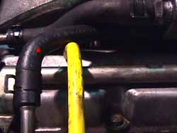
37. Install the new rubber water lines, the double 90 degree bend goes on the front water feed line (2 x hoseclamp), the double angle one goes on the rear water feed line with the yellow dotted end going to the front/top (2 x hoseclamp) (16.).
38. Re-attach the bracket on the rear water feed line. Tighten the water feed line banjo bolts (2 x 19mm). Torque to 11-14 ft-lbs.
39. Remove old oil return line rubber coupling (1 x hoseclamp). Replace the rubber coupling hose for the oil return line on the oil pan (2 x hoseclamp). Install the oil return tube (2 x 12mm, 1 hoseclamp) and gasket. Torque bolts to 12-15 ft-lbs.
40. Twist the oil feed block coming from the block back to horizontal (red dot in 13.). Start the front fitting of the oil feed line into the top of the turbo. Prime the turbo with oil just like the driver side. Install oil feed tube banjo bolt (1 x 19mm banjo bolt). Note: This is the set of copper seals that has the 'bridge' on it. Torque to 11-14 ft-lbs. Tighten the front fitting (1 x 12 tubing wrench). Torque to 11-13 ft-lbs.
41. Install the heat shield bracket to the compressor side (2 x 10) (17.). Torque to 18-22ft-lbs. This seems excessive, but that's the spec. in the '95 manual. They really don't want the shield coming off!
42. Install the intake inlet (2 x 12mm), with gasket. Torque to 18-22 ft-lbs. Cap off vacuum nipple, or re-attach to the stock boost solenoid, depending on needs. Re-connect the vacuum line from the boost solenoid. If running an EVC full time, cap the nipple instead (9.). Stuff a rag in the open end to keep debris from entering the turbo.
43. Install new intake outlet rubber hose coupling (hoseclamp assembly or 2 hoseclamps, depending on if the assembly is still together). Leave clamps loose. Install the intake hardpipe in the other end of the coupling, bolt to plenum (1 x 10mm). Tighten the hoseclamps. Stuff a rag in the open end to keep debris from entering the turbo.
44. Install the pre-cat and gasket (2 x 13mm nuts, 2 x 13mm bolts). Use anti-seize compound on the nuts & bolts. Torque to 18-22 ft-lbs. Install the heat shielding (3 x 10mm) (10.). Torque to 4.6-6.1 ft-lbs.
45. Don't forget to tighten the intake outlet clamps when the engine is going back into the chassis.
Rev. 5-9-2000
© Twin Turbo Zs of Dallas - All Rights Reserved 2000
2.
3.
4.
5.
6.
7.
8.
9.
10.
11.
12.
13.
14.
15.
16.
17.